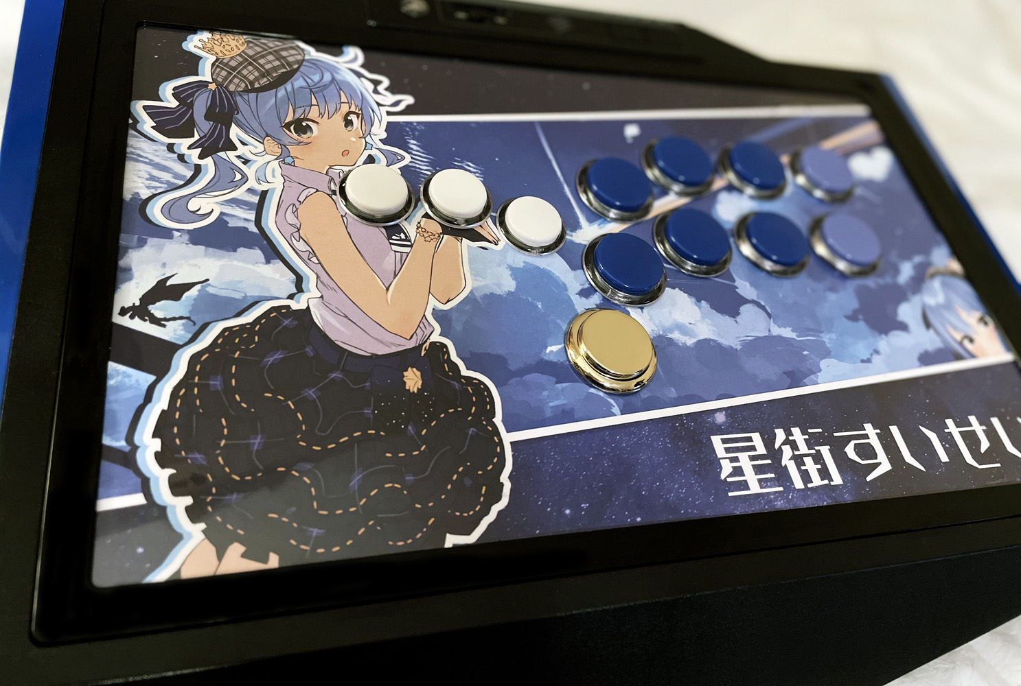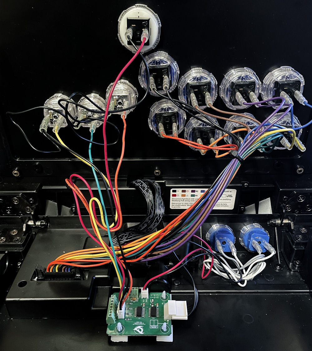
The story about how I ended up not only with a fight stick again, but also converting it to stickless/hitbox-style, is long and convoluted. Instead, I’ll just document how I went about doing so.
Forewarning: I’m not an electrician. Performing this mod at under your own risk.
To cut to the chase, you really only need 3 things.
- A means of putting buttons in place.
- A 5-pin “All-Button” conversion harness.
- An SOCD cleaner.
>>>>Skip to getting +5 Volts for SOCD<<<<
#1. Putting Buttons in Place
With TE2 sticks, the control portion is divided into four parts. There is the bezel–which in my case is the black plastic outline in the picture above. The Acrylic panel. The art layer. And finally, the metal inner plate itself.
With mine, I used a Jasen’s Customs conversion kit which replaces the metal panel and acrylic top. Both of which sit underneath the bezel. That store is long defunct at this point though. The only other means I know of adding button mounts is the Stickless Panel from AllFightSticks. It has an accompanying acrylic top panel (sold separately). This AFS solution replaces the metal plate and bezel entirely to sit flush with the rest of the body. The acrylic panel, when mounted on top, will stick up 1.5mm above the flush surface.
Removing the individual layers here is rather self-explanatory. The order of removal is Bezel -> Acrylic panel -> Art -> Metal plate.
In my setup, I run 5x Crown SDB-202C MX 24mm buttons and 9x Crown SDB-202C MX 30mm in a Vewlix Shiokenstar layout. The two extra 24mm buttons are for Start/Options. MX Speed Silvers in actions. MX Reds in movement.
#2. 5-Pin Conversion Harness*
If you have a Brook board, you really only need the 5-Pin harness itself. But if you have a Brook board in a TE2 already…you wouldn’t need to even read this. Anyway… You connect the shared ground leads to each button, then the colored wires. If you’re connecting to a Brook board or the stock one, the color order is: Yellow = Left, Pink/Red = Down, Green = Right, Orange = Up.
Some other custom harnesses have different lengths of wire per color to make it easier to connect. HOWEVER. Because we intend to use a separate SOCD, we must use a different harness that terminates with a female 5-pin JST connector or convert the one linked above with a 5-pin female-to-female cable.
#3. SOCD Cleaner
SOCD stands for Simultaneous Opposite Cardinal Direction (Cleaner), and what it does is makes sure your inputs aren’t doing things a normal fight stick can’t. Think: holding Back and tapping Forward, it makes charge characters super easy. Pad players can do this, by the way, but somehow it’s cheating when you have giant buttons to clack. Either way, we need this in order to ensure our conversion is in compliance with tournament rulesets. Brook boards all have SOCD cleaning built-in, the literal-named Hitbox has it, and most stickless controllers sold by others have it.
There are numerous standalone SOCD cleaners out there, each with their own pros and cons. I personally used the EZ SOCD, but the main concepts should still be applicable to others. Such as: FA SO.CD, MAS SOCD, and Magician’s SOCD.

- Connect the black-cable harness from the fight stick’s PCB itself to the 5-pin male section of the SOCD. (Right)
- Connect the button’s colored harness to the male JST connector. (Left)
- Connect +5 VCC (volts) and Ground. (Middle)
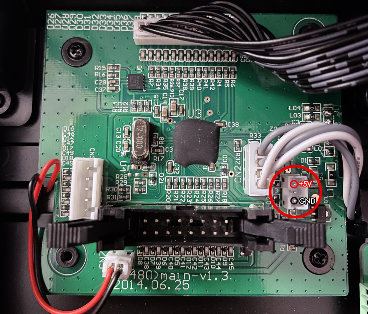
The first two are simple with the advice written way above. Getting voltage from the board is not straightforward, but still simple. Take off the plastic shield covering the PCB and you’ll be met with this.

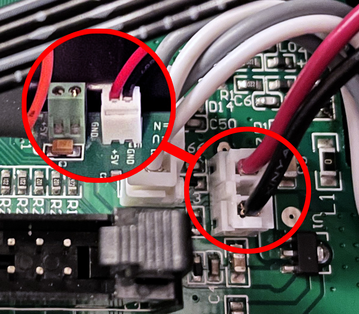
To the right of the big connector in the middle is an empty 3-pin JST connector. The pin closest to the big connector is Ground (GND). The middle is +3V. The top is +5V. This connector is typically used for the LED board in the Killer Instinct version. Using a 2-pin to 3-pin cable, I connected my SOCD as such:

In the above picture, you can see a set of screw connectors to the left of the 2-pin. This is typically what you would see on other SOCD boards. So instead of a 2-pin JST connector, you would take the individual wires and screw them into +5V and GND respectively. And that’s really it.
After connecting this all up, connect your stickless stick to your device of choice and check that the directional buttons are working. If everything went well, it should all work without a hitch. If you’re unfortunate like I was, where my buttons were all messed up, you will have to de-pin the wires from the colored button harness and rearrange them. However, that is out of the scope of this post. But if you contact me somehow about this, I’ll try to help if I can.
Hope this was of use to somebody. 🐬
hello, I do not know if this is still active or if this will reach you but I am trying to do this project and am a bit uneducated when it comes to all this. I was wondering if you could direct me towards a viable cable option for powering the socd cleaner. You said you use a 3pin to 2pin cable but I am struggling to find any available for purchase on the web. If you could provide a link for a viable cable that would be much appreciated.